Specifications
Micro Star makes a variety of nano indenters following defined standards or custom requested geometries and dimensions. Micro Star calibration laboratory complies with the requirements of the International Standard ISO/IEC 17025.

The above is an example of a nano indenter with its three parts, the diamond, the holder and the bond.
Standard nano indenters and custom indenters with applicable geometry are accepted only if the pertinent dimensions and angles are within the ranges specified by the ISO 14577-2 which defines internationally accepted micro and nano indenter tolerances.
There are numerous geometries available for the indenter shape such as three-sided pyramids, four sided pyramids, wedges, cones, cylinders or spheres. The tip end of the indenter can be made sharp, flat, or rounded to a cylindrical or spherical shape.
Diamond and sapphire are the primary materials of Micro Star nano indenters but other hard materials can also be used such as quartz, silicone, tungsten, steel, tungsten carbide, and almost any other hard metal or ceramic. Micro Star also has conductive diamond available.
Nano indenters are mounted on holders which could be the standard design from a manufacturer of nano indenting equipment, or a custom design. Micro Star can design and make the holders or use the those supplied by the customer.
The holder material can be steel, titanium or other suitable material. In most cases Micro Star attaches the indenter to a holder using a rigid metal bonding process.
TIP GEOMETRIES
The tabulated illustrations show most of the indenter geometries available from Micro Star. Each type of indenter is designated by two letters in blue. There are examples of TEM micrographs of critical measured dimensions.
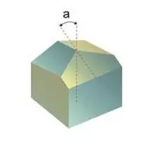
BERKOVICH TB
Berkovich:
a = 65.03°
Mod. Berkovich:
a = 65.27°
CUBE CORNER TC
Cube Corner:
a = 35.26°
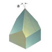
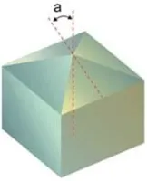
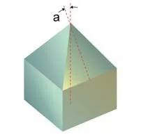
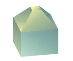
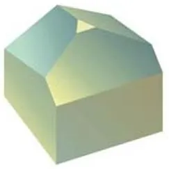
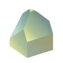
3-SIDED CUSTOM TD
Custom 3-Sided Indenters:
20° < a < 80°
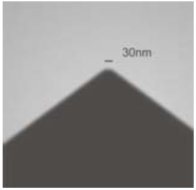
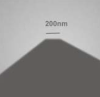
SHARPNESS TEM MICROGRAPH
Micro Star 3-sided sharp indenters tip radius < 50nm.
The above shows sharp point 3-sided pyramidal geometry. The defining angle a is the angle between the axis and any of the faces. The 3 faces are symmetrically placed around the axis 120° apart. The Berkovich indenter is designed to have the same area as the Vickers indenter at any given indentation depth. The modified Berkovich indenter is designed to have the same projected area as the Vickers indenter at any given indentation depth.
Micro Star makes a wide range of 3-sided indenters with custom angles and flat or round ends of any compatible size.
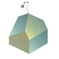
VICKERS FV
Standard Vickers indenter:
a = 68.00°
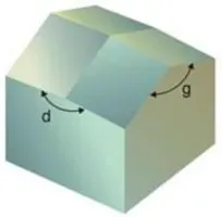
KNOOP FK
Standard Knoop indenter defined by 2 angles:
d = 172.50°, g = 13.00°
4-SIDED CUSTOM FD
Custom 4-sided indenters:
80° > a > 20°
END LINE TEM MICROGRAPH
Micro Star indenters maximum line of conjunction: 400nm.
The above shows sharp 4-sided geometries. Most 4-sided indenters have their faces symmetrically placed around the axis 90° apart and the defining angle a is measured between the axis and each face. The standard Knoop indenter has a special geometry as shown.
The apex of a sharp 4-sided pyramidal tip is typically a small line (shown on the TEM micrograph above) called the line of conjunction.
4-SIDE FLAT END FP
Flat 4-side square from 500nm to 200µm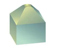
4-SIDE ROUND END
End radius from 100nm to any compatible size.
3-SIDE FLAT END TP
Flat triangle from 300nm side to any compatible size.
3-SIDE ROUND END TR
End radius from 100nm to any compatible value.
The above shows 3 and 4-sided indenters with flat and rounded tips.
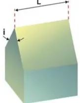
WEDGE WS
End length from 0.3mm to 3mm. Sharp edge radius less than 10nm.
Included angle:
30° < i < 90°
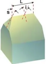
TAPERED WEDGE WT
Wedge with tapered corners. Edge length from 0.5µm to 2mm.
Angles: 30° < i < 90°
15°< s < 45°
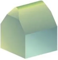
CYLINDRICAL WEDGE WC
Wedge indenter with cylindrical edge angles same as WT.
Radius from 200nm to 5µm.
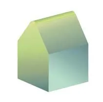
ROUNDED WEDGE WR
Wedge indenter with cylindrical edge and rounded corners.
Radius from 200nm to 5µm.
The above shows wedge indenter configurations.
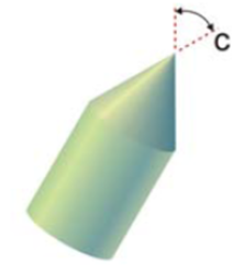
CONE TIP VS
Included conical angle:
20° > c > 140°
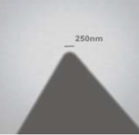
POINT SHARPNESS TEM MICROGRAPH
Micro Star sharp cone radius less than 300nm.
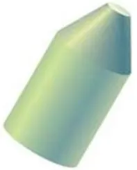
FLAT END CONE VP
Flat from 500nm diameter to larger compatible sizes.
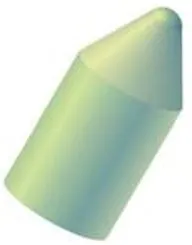
ROUND END CONE VR
Spherical end radius <50nm to larger compatible sizes.
The above shows the general cone geometry with sharp, flat or spherical end. There are no recognized standard angles or sizes for conical indenters.
FILAMENT ROD YS
Thin cylindrical probe 0.4µm < diameter < 10µm. Straight section up to 50µm long. End not defined.
CONE END ROD VS
Straight cone at end of cylindrical section. Most Micro Star cone indenters (Type V) are made this way.
FLAT END ROD YP
Diameter from 20µm to 200µm. Straight section up to 0.3mm long.
ROUND END ROD YR
Spherical end rod. Diameter from 40µm to larger compatible sizes. Straight section up to 0.3mm long.
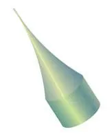
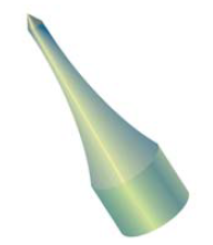
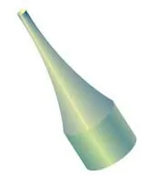
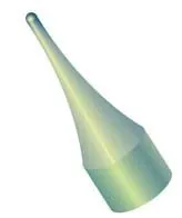
Many Micro Star nano indenters are made at the end of a taper cone. The small volume of material to be shaped to a particular geometry provides higher precision and minimizes anisotropic effects.
DIAMOND AND OTHER MATERIALS
Diamond is the primary material for nano indentation. Only single crystal diamond, free of impurities or inclusions is used. Most Micro Star diamond nano indenters are shaped at one end of a large square section prism, as seen on some of the illustrations.
Diamond indenters are accurately aligned with the atomic crystal orientation such that the axis is in line with the 100 directions. One face of 3-sided and all four faces of 4-sided indenters follow the 100 crystal direction. Other crystal orientations are available at customer request.

Diamond Atomic 100 Crystal Directions (dotted lines) that Coincide with Micro Star Indenter’s Axis
The advantages of diamond for nano indentation come from its exceptional properties of hardness, thermal conductivity and chemical inertness, which surpass any other known material.
The strong diamond anisotropy is a disadvantage for circular geometry nano indenters. This applies to conical, cylindrical and spherical indenters. The image below shows the flat “circular” end of a diamond cone indenter (VP or YP Types), compared with the same indenter made of sapphire. If a non circular perimeter shape is acceptable, the diamond indenter can be made to a precise area specification in square microns. With diamond, it is possible to approach circular or spherical geometries but at higher cost.

Diamond 4-sided Anisotropy – A diamond “circular” flat end becomes almost a square (left). Sapphire can approach a perfect circle.

Micro Star has electrically conductive diamond available. The conductivity comes from Boron ions dispersed through the bulk of the material not just from surface coating. Conductivity is required in some special applications and to prevent static charge distortion of measurements. The resistivity is 0.04 Ohm•m, similar to graphite.
Sapphire is the second material available for Micro Star nano indenters. Although not as hard as diamond, sapphire can be shaped to similarly sharp points and edges. Micro Star sapphire indenters are made with the crystal C axis aligned with the indenter axis. The anisotropy of sapphire is much weaker than diamond permitting nearly perfect spherical and circular shapes. The images above compare some diamond and sapphire properties.
HANDLING AND CLEANING
Micro Star nano indenters are made to probe materials properties at nanometer scale. It follows that a basic requirement is the total absence of debris and particle contamination which would affect the indenter’s performance in two ways.
a) Distorting the measurements because contaminating material adds an unknown factor negating the precise geometry of a clean indenter.
b) Damaging the indenter as debris particles are crushed between the indenter and the sample, producing lateral forces which the nanometer size tip is not designed to withstand.
Before shipment, Micro Star indenters are cleaned and inspected at high magnification. The user needs to maintain a clean and undamaged probe to acquire accurate test results.

Indenter Protective Packaging
The indenters are supplied in special protective packaging, see above. The tip is protected from contact with other objects by the tube as shown. This tube fits lightly on the cylindrical part of the holder. The tube may be used as a handle to attach the indenter to the instrument and then remove it with a straight motion avoiding touching the tip.

Indenter Cleaning with a Cotton Swab
If the diamond nano indenter is properly handled, it should not require cleaning. If it nevertheless becomes contaminated, clean as follows:
Looking through a stereo microscope, rub the diamond with a cotton swab soaked with isopropyl alcohol. Before the alcohol dries, blow the tip with pressurized air or other clean gas.
Inspect the diamond with an optical microscope at 400X. Repeat cleaning if necessary. Do not use the indenter unless the tip is totally clean and free of debris.
SPECIFICATIONS AND TOLERANCES
Micro Star indenters are measured with instruments calibrated with standards. The angles are measured with a specially designed goniometer. Linear dimensions are measured with calibrated optical microscopes or SEMs.
Each Micro Star indenter is measured individually for all pertinent dimensions. The figure below shows the angles and nomenclature used on a 3-sided indenter. The specification sheet below is issued with each indenter. Sample data from a cube corner indenter is shown.

Angle Measurements on a 3-sided Indenter (for clarity, not all the angles are shown).
Below is a table of the symbols used with Micro Star indenter measurements and specifications with the ISO required and Micro Star standard tolerances. Smaller tolerances are available for some indenters at extra cost.
The tolerances of all specified angular or linear dimensions meet or exceed ISO 14577-2 which defines internationally accepted micro and nano indenter tolerances.
STANDARD NANO INDENTERS
Micro Star can provide the Berkovich, Modified Berkovich, Cube Corner, and Vickers indenters following the definitions of ISO 14577-22.
A Calibration Certificate accompanying these indenters covers the following items pertaining to the particular indenter:
a) Table of measurements.
b) Uncertainty of measurements.
c) Confidence level of measurements.
d) Measuring methods.
e) Measuring instruments.
f) Inspector’s signature and date.

Indenter Specification Sheet with Example Data in Blue

Footnotes:
- ISO/IEC 17025 = International standard comprising general requirements for the competence of testing and calibration laboratories.
- ISO 14577-2 = Instrumented indentation test for hardness and materials parameters. Part 2: Verification and calibration of testing machines. In particular section 4: Direct verification and calibration.
- TEM = Transmission Electron Microscope.
Berkovich, E. S., Three faceted diamond pyramid for micro hardness testing Industrial Diamond Review, 11, #127, June 1951. - Oliver, W.C. and Pharr, G.M., An improved technique for determining hardness and elastic modulus using load and displacement sensing indentation experiments. J Mater. Res.,7, #6, June 1992, pp 1564-1583.
- Anisotropy = The change of crystal properties with atomic directions. Anisotropy is especially pronounced in diamond with different abrasion resistance depending on the crystal orientation.
- AFM = Atomic Force Microscope
- Conductive diamond available from Micro Star.
- SEM = Scanning Electron Microscope
NANO INDENTER PHOTOGRAPHS

Berkovich Diamond Indenter

≤20nm Radius Diamond Cube Corner

≤20nm Radius Diamond Cube Corner

3-Sided Custom Indenter

Taper Cone Diamond Indenter – The cylindrical end is 20µm diameter and 60µm long.

Diamond Cone Indenter – 90° angle and 5µm end radius. Formed on a 200µm diameter rod.